Week 3 : Computer-controlled cutting
the assignment for this week are:
The group assignment
- Test and calibrate the Laser cutter that we are going to use
The individual assignment
- Make a 3D design that can't be done with a subtractive manufacturing technologies (using the CNC, the Laser cutter, etc...) and print it with a 3D printer.
- cut something on the vinylcutter
- Design, lasercut, and document a parametric construction kit(accounting for the lasercutter kerf)
Groupe assignment
The direct link to the groupe assignmentHere's a brief summary on what we've done so far !!!
It was the first time that we had to work on something as a group; we got to work with the laser cutter this time and to test how it works , its V-ray cutting and its dimensions.
HARDWARE
Laser cutter CO2
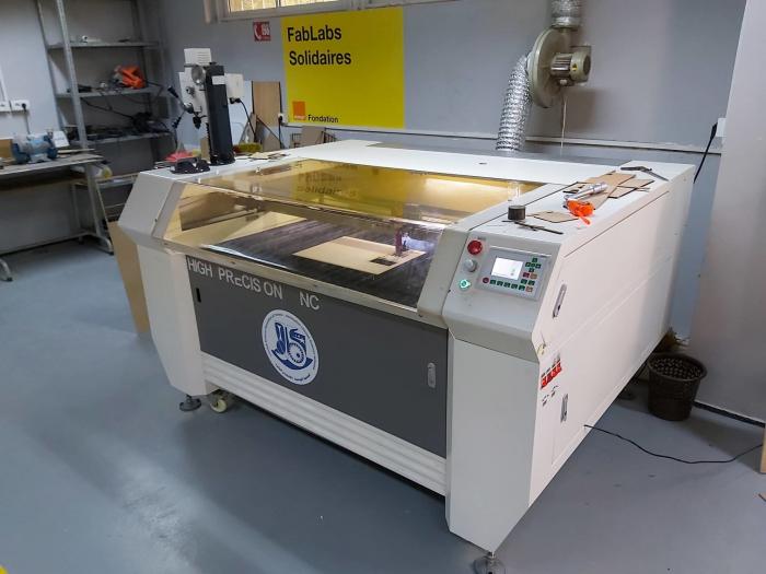
Class: 3R (for this class, lasers are considered safe when handled carefully. There is only a small hazard potential for accidental exposure. For visible-light lasers, Class 3R lasers’ output power is between 1 and 4.99 milliwatts.
Laser Power: 100 Watt
Model: Golden Sign GS9070
Materials: Plywood/Mdf 4mm; Cardboard 6mm; Plexiglass 5mm
1- Switch ON the laser
2- Switch ON the pointer
3- Unlock the X/Y motor axes
4-Move the X/Y axes to set the users’ origin, in the upper left corner of the piece that you want to cut, then SET it with Origin Button, this helps you with the pointer
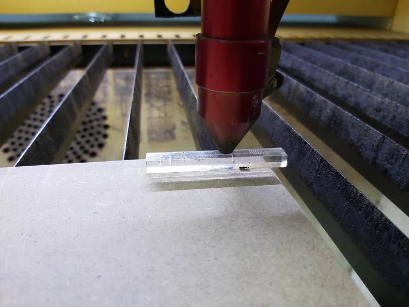
5- Use some material pieces(like a piece of plexiglass) with different sizes to the engraving target to find the correct beam focus point that helps (5mm in our case) to set the machine to a given height above the material.
SOFTWARE
FUSION360
Before using the machine, we started designing our own Test Template using Fusion 360 in a 2D sketching.
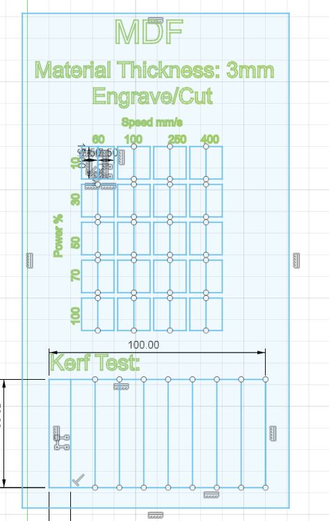
Of course, we looked for other open source laser test templates to have ideas about how are we going to test our laser cutter. And we made our own template afterwards, we chose to test cutting and engraving at the same time on a MDF (3mm) with different speed and laser power for each rectangle, then exported the sketch as a DXF format.
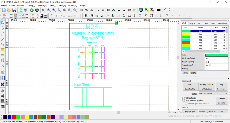
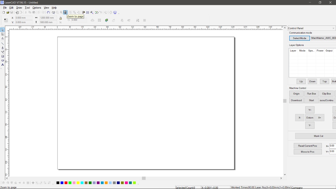
LASERCAD
Now it’s the time for the Software(we used LaserCAD) to set the laser cutter settings of the power, the speed and the frequency per different color.
However, this software is definitely not the best to be used, we got some problems while making the test template; the colors options and the number of layers is very limited, and the software can only recognize the lines that are thinner than a DPI-dependent threshold. Though our test template required so many different settings in other words ,many different colors. Thus we had to use multiple colored layers to test different powers and speeds. Therefore we used ADOBE ILLUSTRATOR to make a varity of colors and to set every color with a specific setting of power and speed
And now it’s the time for the results
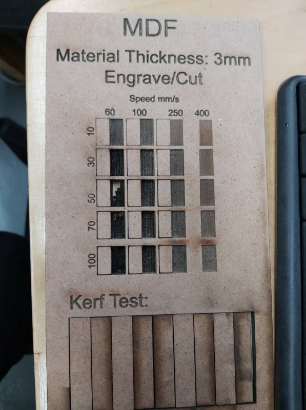
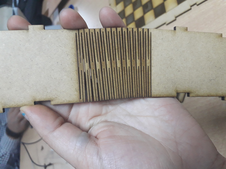
We made a KERF test too to determine how much is the amount of woods that”s removed by the laser while doing its JOB
So in other words THE KERFis the amount of wood removed by the laser cutter as it burns through the wood. Thicker pieces of wood or plywood which has glue require a slower laser cutter speed and higher power will burn away more wood, making the kerf wider.
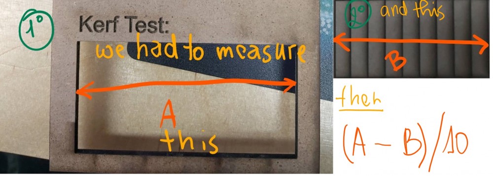
We found that the Kerf is 0,3 mm
Individual Assignment
LASER CUTTER
FIRST attempt:
This was the most fun part, we had to make anything using the laser cutter.
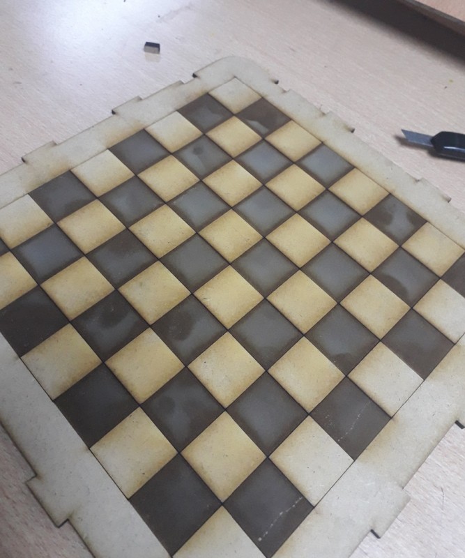
I wasn't so sure about what I'm going to do at first, however I've decided for this part to make a medium sized Chessboard box and for that I needed to fully take the exact measurements into consideration while doing that. But first of all we had to design the model using FUSION 360
Here are few things that I learned to not DO with this week’s assignment and you have to be cautious about, while preparing your model!
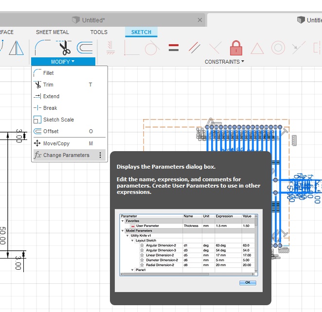
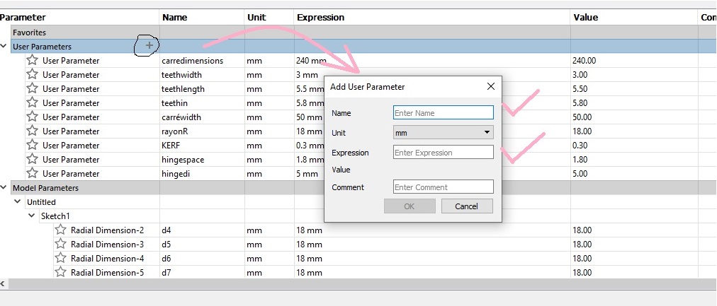
First, while you are using Fusion 360, one of the best thing you have to do, is making your dimensions personalized, in other word, fixed (this saves time and energy when you want to change your dimensions automatically)MODIFY>CHANGE PARAMETERS:
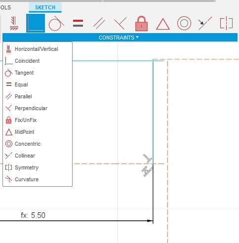
Second, you can also use the CONSTRAINTS menu
As I said, I wanted to make a chessboard, which was not quite what I was expecting to be and it turned to be a total failure!
Therefore,
SECOND attempt:
It was quite unpleasent too!!!
THIRD attempt:
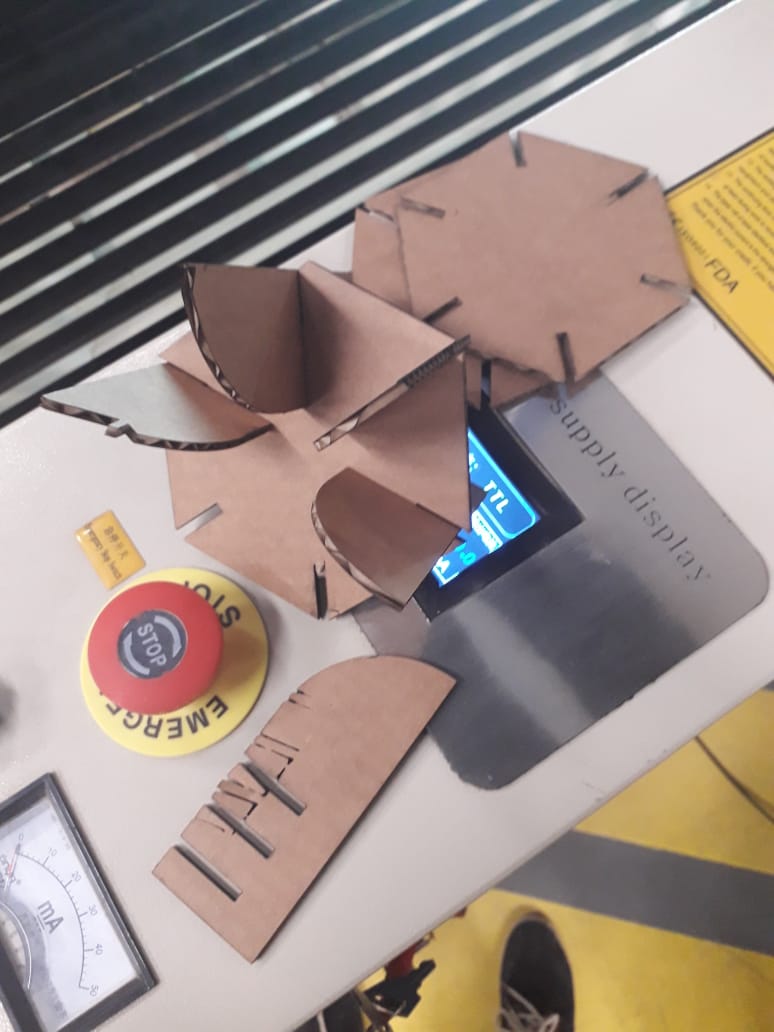
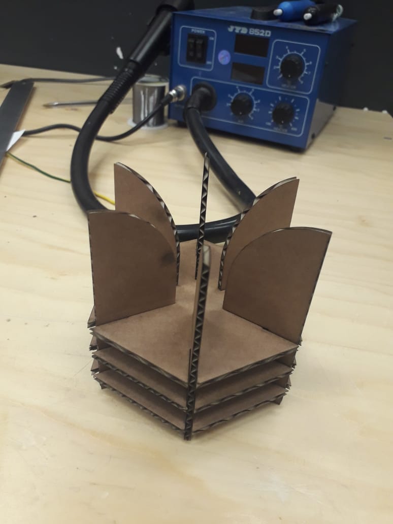
As my third attempt for this assignment, I decided that I'm going to simply use card board in place of MDF since it's so cheap, and it's so easy to work with!
So for this fresh start, I'm going to explain everything from begining:
I used Fusion360 as usual
.png)
.png)
.png)
.png)
.png)
.png)
Then you have to save your model as a DXF format to be prepared to be used in the LaserCad and to set your desired sittings.
.png)
And now my model is ready.
There's some work you need to do before sending the file into cutting
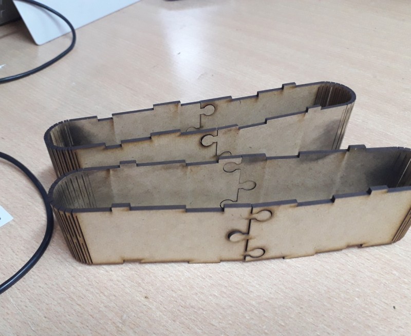
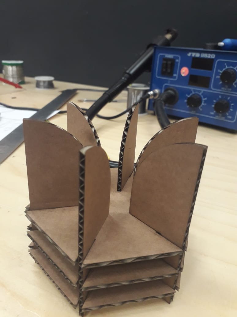
And since I only made one copy of everything: I needed six of "hands" and 3 of "bases" for the KIT to be ready. All what you have to do is clicking on the four square bottom Array clone and make copies as you want in the direction that you want
.jpg)
And since I forgot to delete the construction lines on Fusion. I decided to delete them here.
PS: LaserCAD has so limited options to use and it was a total waste of time to try doing that here, so I used fUSION once again and I repeated the whole thing from the beginning.
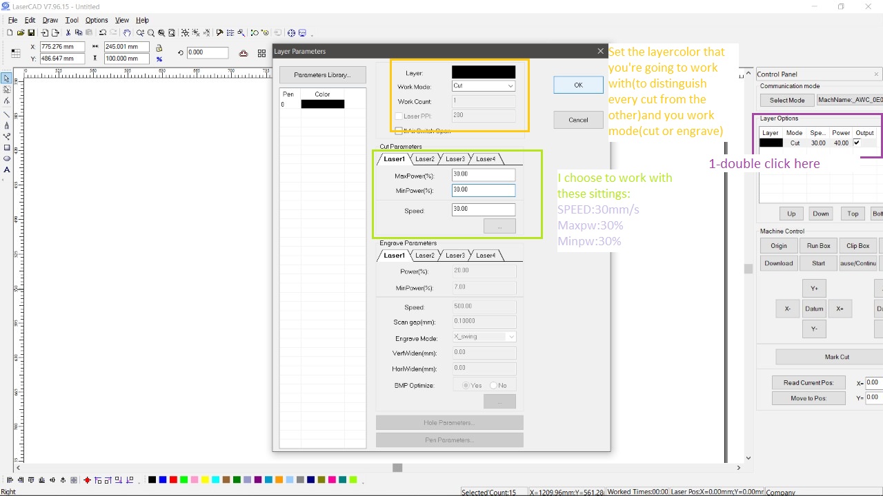
All what I had to do now is setting the parametrs of the SPEED, and POWER
Go to the Control panel and Double click under the Layer option on the black rectangle(that represents the color panel of the cut)
Since I'm only going to use the LASER CUTER to cut out only the outlines.
I only needed to make an only layer and set it in a CUT mode.
As for the SPEED and POWER parameters:
I choose the lowest values since I was using cardboard!
SPEED:30 mm/s
Max & Min POWER:30 %
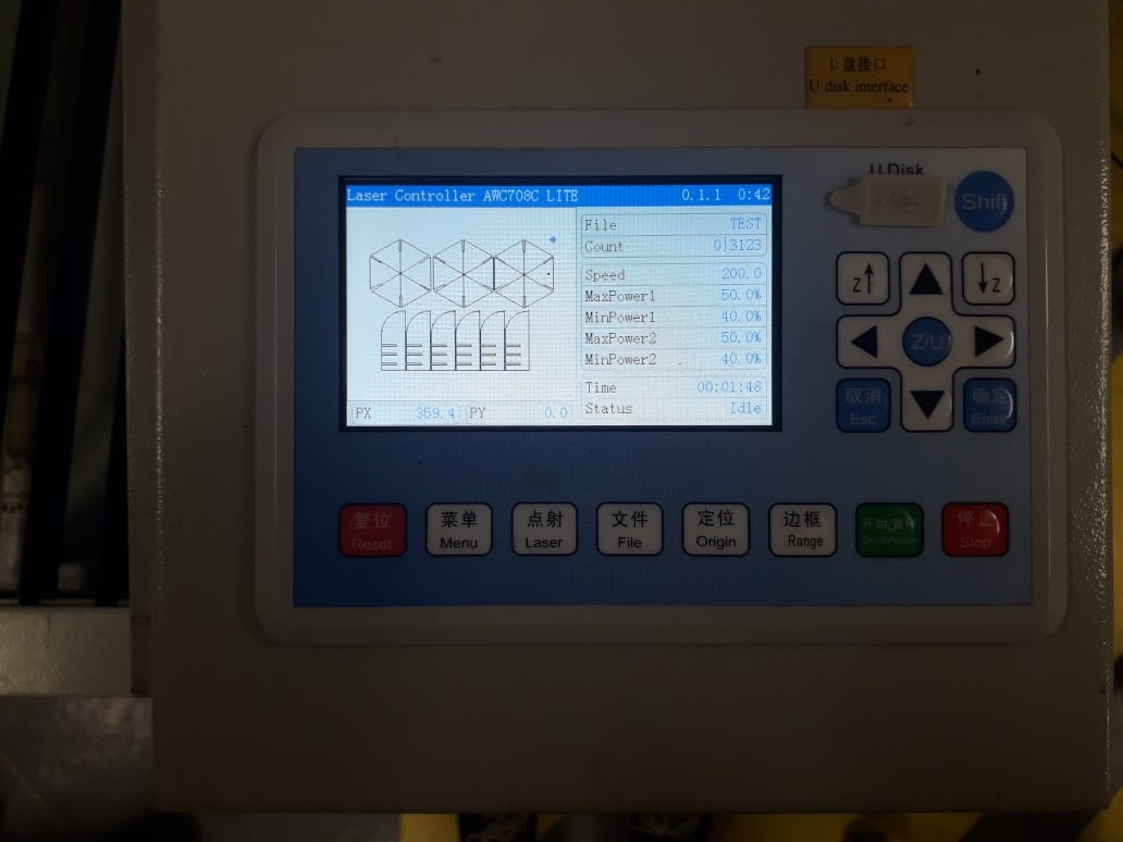
Afterwards, I sent the file to the Lasercutter by clicking on Download!
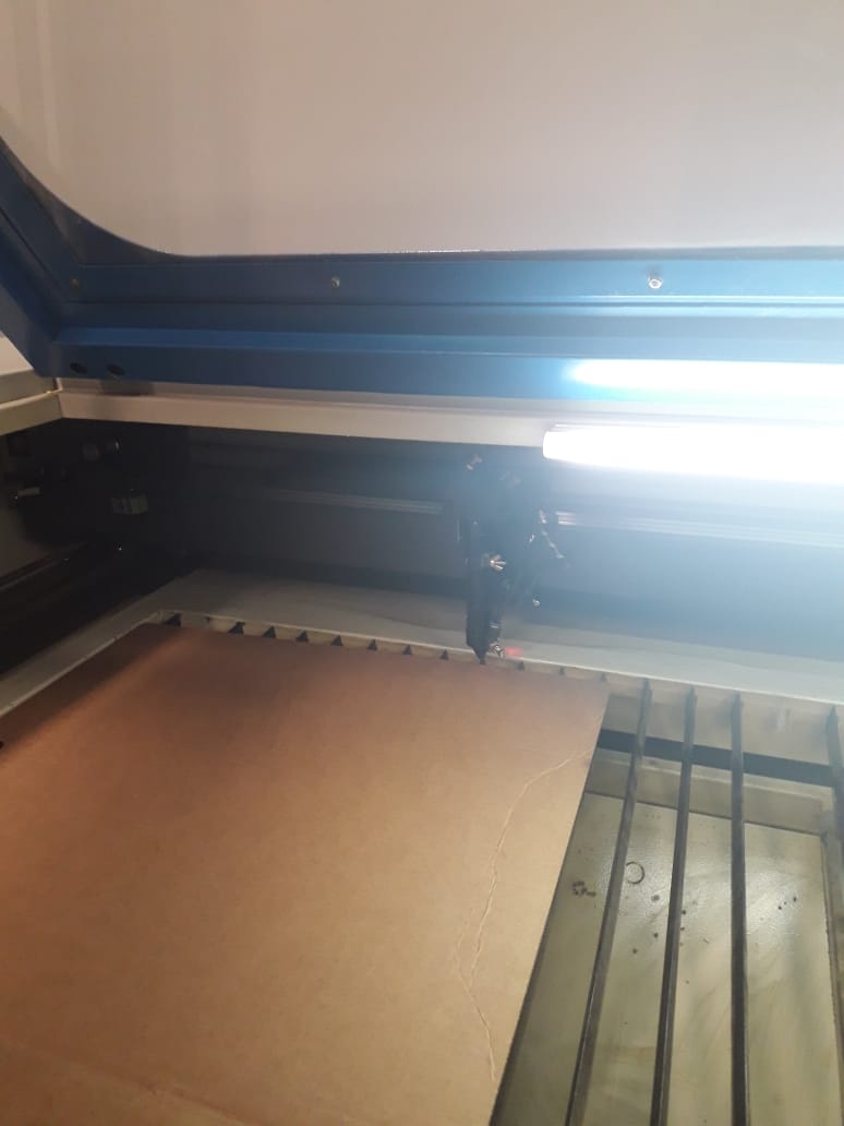
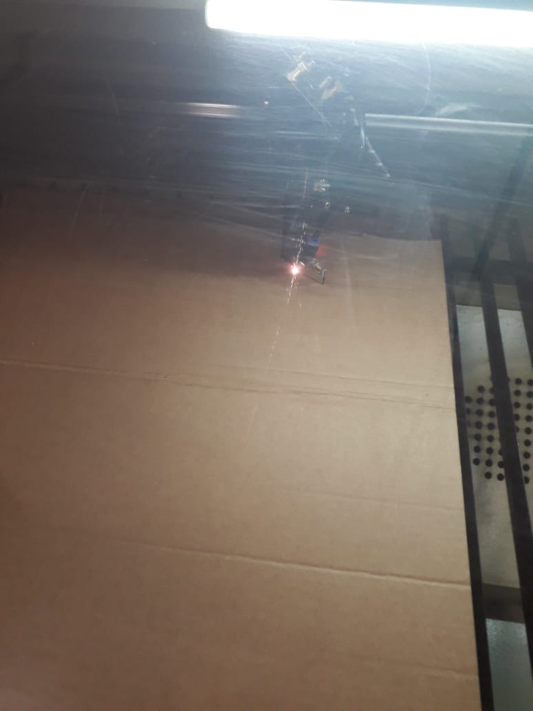
And now It's time for cutting.
And then, it's ready to be cut by the laser.
And then sending it to the machine to start cutting
PS: I took photos of my first try when I noticed that I didn't delete the construction lines
But first of all, we have to make sure that the pointer is in the right path!
You have to change manually the positing of the laser pointer by clicking on those:
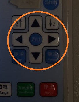
Then, you have to make sure that the pointer is fixed in the position that you already set it for it by clicking on Origin
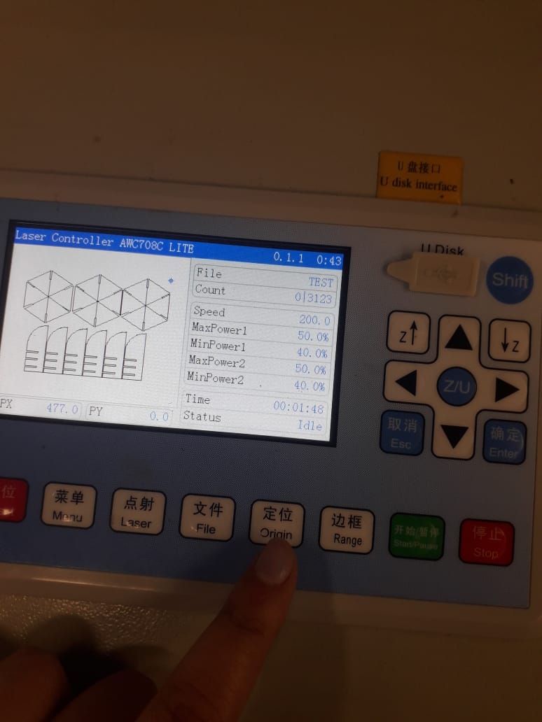
And by clicking on RANGE you would know the direction of the cut, the dimensions and laser cutters place of work.
RESULT!
VINYL CUTTER
- Hardware: we used the Vinyl cutter"Roland GS-24"model!
- Material: Vinyl, which is a thin self-adhesive plastic!
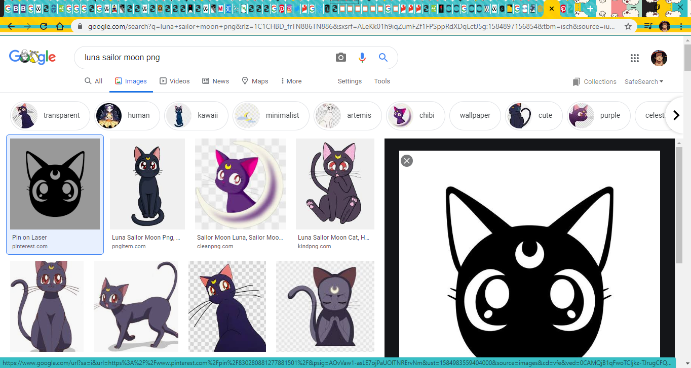
- How it works?: controlled by the computer, the vinyl cutter is like a printer that instead of ink it has sharp blade that moves over the surface of the material that I wanted to be cut. I choose a photo from internet.
- Software: Roland CutStudio is the Software used in setting this Vinyl cutter.
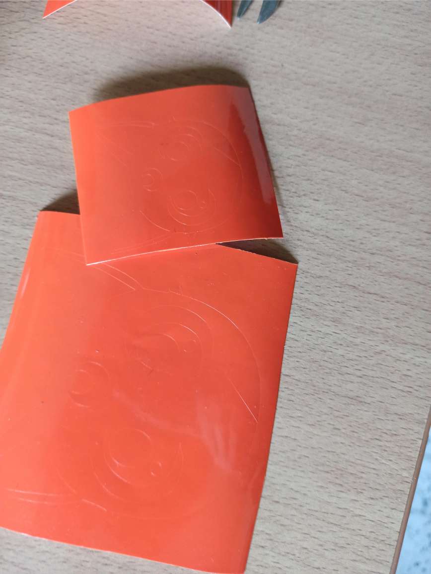
- Removing the unwanted parts: Afterwards, I needed to remove the negativ parts to get the wanted result; I used some parts of a MASKING TAPE that I found in the LAB!

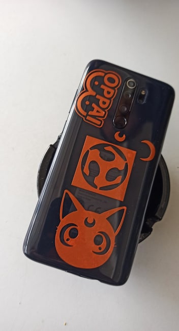
Since I'm such a cat and anime lover; I choose one of my favorite childhood characters to make a sticker out of it!
I found it on PINTREST!
Result:
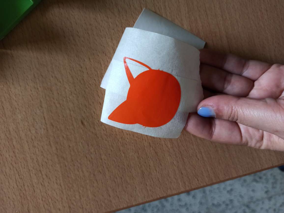
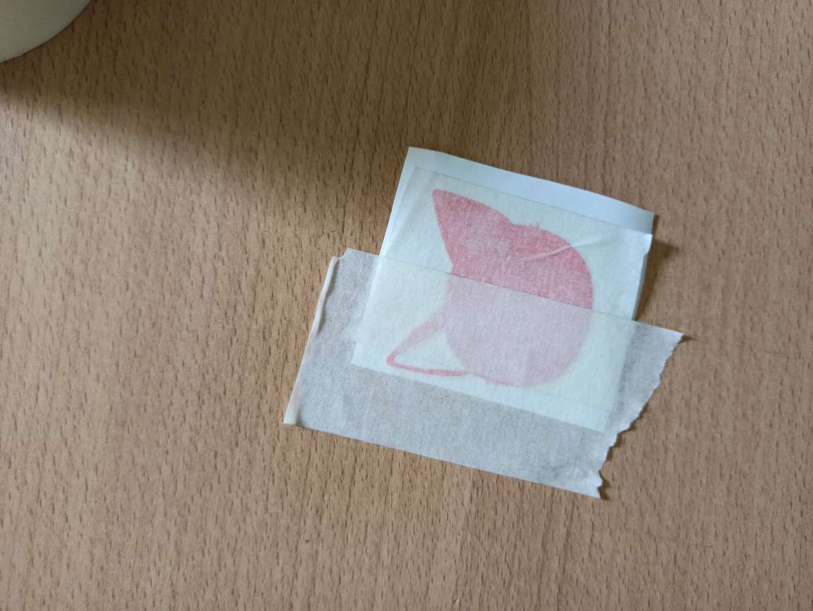
Just put it wherever you want.
.jpg)
.jpg)
Yeaaay!!!